GBE0/1_CTREF pins connection of I-Pi SMARC carrier board
-
Attached is the schematic of the Ethernet-related circuitry near the RJ45 connectors on the I-Pi SMARC carrier board.
In the diagram, resistors R801, R802, R803, and R804 are marked as "NI", (I expect) indicating they are not implemented. As a result, the GBE0_CTREF and GBE1_CTREF pins appear to be clamped to ground through the parallel capacitor pairs C801/C804 and C802/C803, respectively.
I would like to confirm: does the "NI" marking on these resistors indeed mean they are "not implemented" in this schematic?
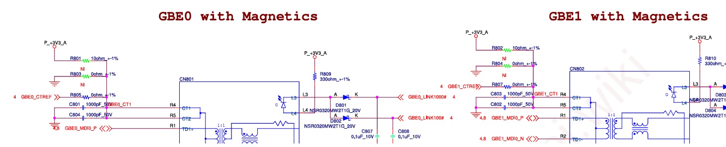
* Attached is the diagram on page 8 of I-Pi SMARC carrier board schematic drawings.
-
 Master of SMARC Staff member
Please login to reply to this topic!